How to build a homemade Nest thermostat
Want a smart thermostat on the cheap? You can make your own for less than £50 with a Raspberry Pi
Home is where the smart is these days, and one of the easiest ways to give your house a brain boost is by upgrading the heating system.
You could do that by buying an off-the-shelf thermostat from Nest, Honeywell, Netatmo, Hive or the like – check out our comprehensive smart heating test for more on them – or you could spend less and have more fun building a smart thermostat using a Raspberry Pi.
Fancy option two? Of course you do…
Overview
We’re going to use Nest as our main comparison thermostat, so we’re going to call our Pi-powererd verson ‘PiNest’.
PiNest will use Google Calendar events to set a schedule, and because some of Nest’s more interesting smart features harness the power of If This Then That (IFTTT.com) recipes, ours will tie in with this as well.
It’s not going to be shiny and perfect like a Nest or Hive, and it doesn’t (yet) learn your schedule, but it’s a great starting point for your smart home which you can add to as time goes on. We’ll keep adding to ours and will let you know how we get on.
We’ve tried to do this in the way that requires the least programming possible, so even a complete beginner can do it. That’s one of the reason’s we’re using Google Calendar, IFTTT and email to send the temperature commands, plus a single Python file to control the Raspberry Pi.
In a nutshell: a scheduled heating event in Google Calendar triggers IFTTT to send an email which your PiNest reads, then switches your heating on or off accordingly.
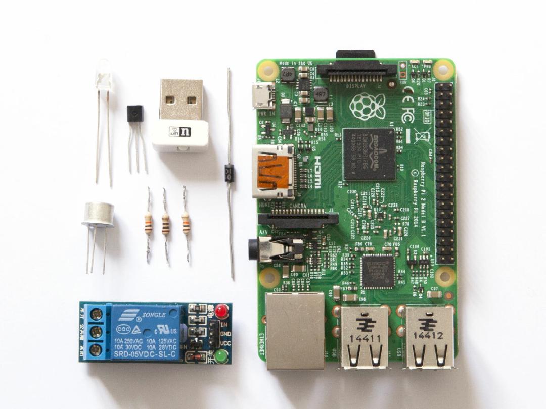
Component list
RELATED › The best smart heating systems – tested
Set the heating schedule with Google Calendar
Set up a new calendar named ‘PiNest’ (or whatever you’d like to call it). Within that calendar, add repeating events to set the temperature.
The name of each event should be the desired temperature e.g. the event ‘20′ at 08:00 every day will set the heating to 20 degrees at 8am every morning. Setting other events called ‘0′ will turn it off again.
You could skip this step and just set time-based recipes on IFTTT but, especially if you’re a regular Google Calendar user, viewing and changing your schedule using Google Calendar is much quicker than adjusting multiple IFTTT recipes.
Create a new Gmail account
This account will receive temperature event emails from IFTTT, which your Raspberry Pi will read.
Use IFTTT to email your schedule to the PiNest
Sign up for a free IFTTT account and create a recipe that emails your calendar entries to a new Gmail account – you can use this recipe and fill in your own calendar and email settings. The RPi will periodically check this account and compare the target temperature (in the email subject line) to the current temperature, so it knows when to turn on/off the heating. You’ll need to set IFTTT’s email function to use the Gmail account and Google Calendar you’ve just set up.
By using email it also means that you can email the account yourself to set the heating from anywhere without changing the overall schedule. Just write your desired temp, e.g. “21” as the subject and it will send the command to your PiNest. You can also do this with one button press using IFTTT’s Do Button mobile app: assign one button to email “0” and another to email “21”. The PiNest takes its target temperature from the latest command, so this emailed command will last until the next calendar event kicks in.
Setting up the Raspberry Pi
Now that the system for sending temperature commands is taken care of, the Raspberry Pi itself needs your attention.
The hardest part – you’ll need to set up your components on a breadboard to test them. We’d advise you to screw them down to a board if possible to keep everything manageable. The digital thermometer does the temperature sensing, and the rest goes into controlling the boiler.
For setting up and reading the DS18B20 Digital Temperature Sensor, we’ve taken our cues from the excellent tutorial by Simon Monk at Adafruit.
We’ve then combined that with Pete Taylor’s tutorial on setting up the Raspberry Pi to read emails and the fork of his project by GitHub user vwillcox, which empties the inbox once the email has been read.
To start, we’ll assume that you’ve got Raspian Linux installed on your Raspberry Pi (if you’ve not done that yet, see instructions here – beginners should start with a NOOBS installation) and that you’re working with the Raspberry Pi 2 Model B, which is the version that we used.
As we’re using WiringPi’s GPIO numbering system there shouldn’t be much difference, though. You’ll also need your RPi connected to your network via an Ethernet cable or USB Wi-Fi dongle. For the latter you’ll need to configure your settings within Raspbian’s GUI.
RELATED › 5 of the best Raspberry Pi projects
Wiring up the components
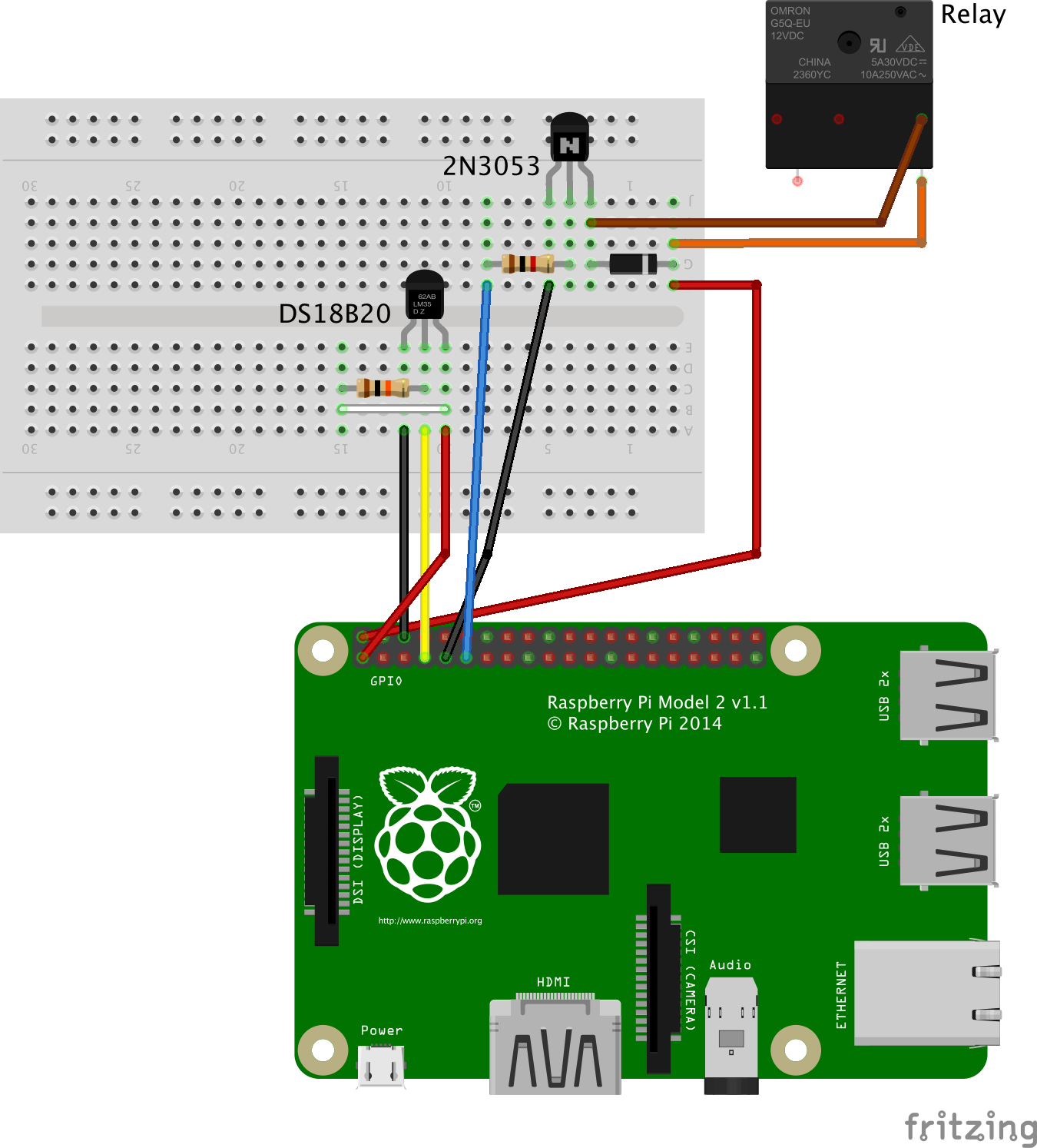
Wire up the components on your breadboard as shown in the diagram. All the connections are included apart from the one from the relay to the boiler.
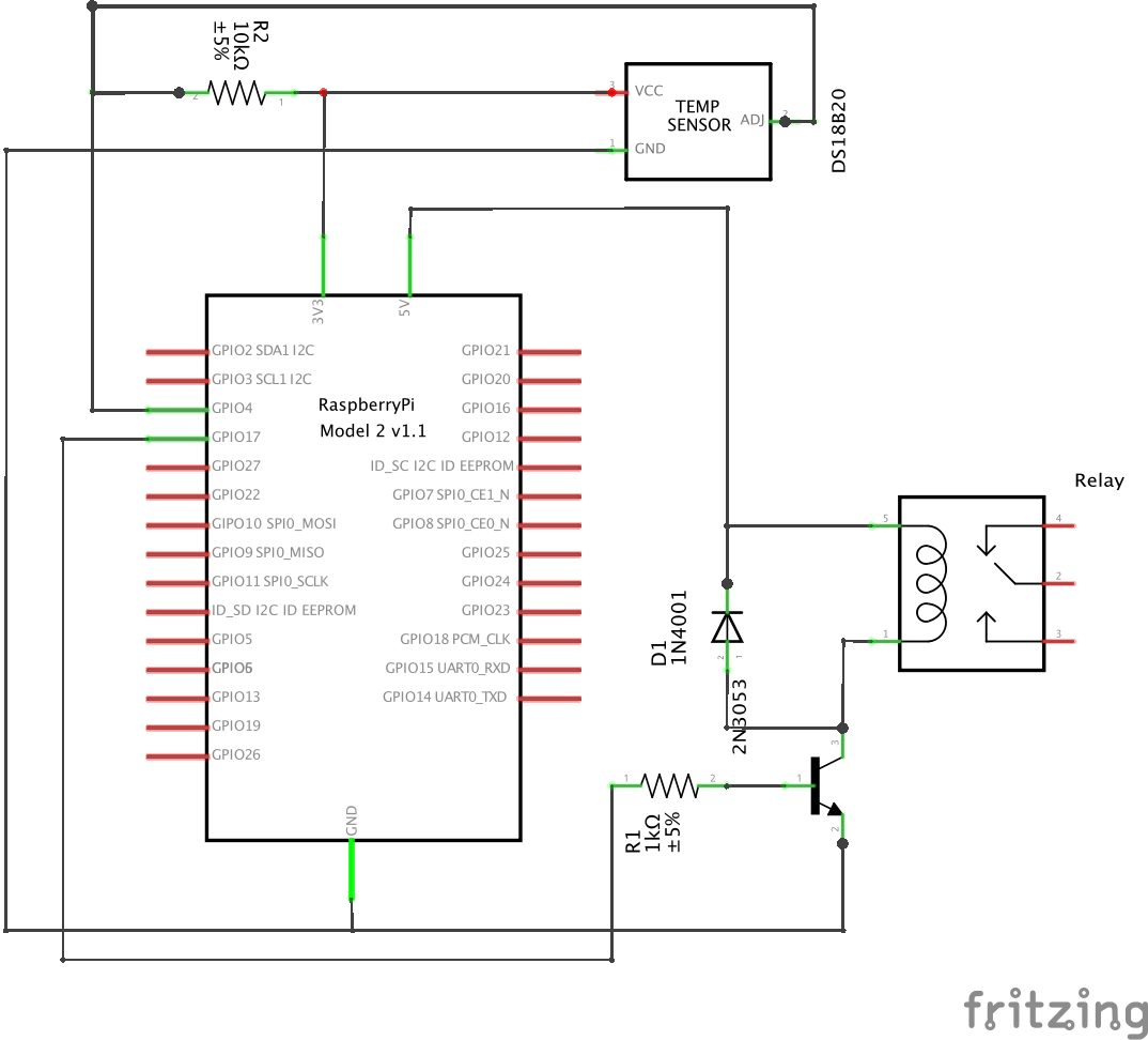
Pay particular attention to the orientation of the transistor and digital thermometer. Your digital thermometer should be placed exactly as in the diagram with its flat side towards you, but your transistor may be the larger, round type, so make sure you double-check you’ve connected it the correct way by comparing the schematic below with the diagram on your transistor’s data sheet.
RELATED › Raspberry Pi 2 review
Schematic
Configuring the Raspberry Pi
Before our thermostat program will run, we have to configure the Raspberry Pi. You’ll have to do this via the command line (aka terminal window). If this is your first time, read raspberrypi.org’s explanation.
The indented text below denotes that it is what you should type into the terminal window.
1. Make sure you have the latest updates
sudo apt-get update
2. Enable SPI and i2C protocols
In the terminal window, type:
sudo raspi-config
Select Advanced Options, then enable both SPI and i2C
Select finish to reboot. Once it’s restarted, test installation with:
gpio load spi
gpio load i2c
If the above two return nothing, drivers are working okay. If they produce errors, try following Adafruit’s manual i2C and SPIconfiguration instructions.
3. Install Github
This is needed for the installation of the WiringPi library.
sudo apt-get install git-core
4. Install the WiringPi library and Python
git clone git://git.drogon.net/wiringPi
cd wiringPi
./build
Install Python:
cd
sudo apt-get install python-dev python-pip
Press y to confirm, enter
Install WiringPi2:
sudo pip install wiringpi2
Check installation of WiringPi2 (should return RPi board number e.g. "2"):
sudo python import wiringpi2
wiringpi2.piBoardRev()
Press ctrl+d to exit python
Test setup by typing the following:
gpio readall
You should see a rundown of the pinouts.
Establish contact with the digital thermometer:
Add the code and run the program
Now that your Raspberry Pi is set up, it’s time to load the Python file that controls your thermostat.
You can find the code for the file here on GitHub.
Open a new file called pinest.py with the following command:
sudo nano python pinest.py
Copy in the code from the GitHub link above. You’ll need to edit the email address and password within the code file to match your new Gmail address. Save and close it, then run your program:
sudo python pinest.py
It should start displaying current temp, target temp and whether the heating (relay) is on or off. It will repeat this every five seconds. You should hear the relay clicking when it changes between on and off. You can test this by emailing a new target temperature to your new gmail account.
It may have trouble running if there are no emails in the account (cannot find var subject), or if there are too many to process. Starting with one email in the inbox should solve this.
Connect to your boiler
Once you’ve checked pinest.py is running properly and your relay is turning on and off as it should – you may want to connect an LED and resistor in place of the boiler circuit to make sure – the last step is to connect it to your boiler.
This last step is the most important to get right, because to control your heating the relay must be connected to the control circuit on your boiler. If, like us, you’re not a plumber or an electrician, we’d advise finding someone who is to help you do this bit. Mains electricity can be the end of you, so don’t take any chances.
The only part of your circuit that should have any contact with the boiler circuit is your relay. Do not connect mains voltage to your breadboard – it is absolutely not designed to handle anything over about 15V.
You’ll need your boiler’s instructions for a wiring diagram of where to attach a programmable thermostat.
Let us know how you get on and give us a shout if you have any suggestions or additions to this project.
NOW ADD THESE
1. By experiementing with IFTTT recipes, you can set more complex behaviours such as using your phone’s GPS to tell the PiNest to turn off the heating when you go out. You can find ours here.
2. Once your PiNest is up and running, you don’t have to stop there. Why not add a display (from US$35) and onboard temperature controls? Throw it in a nice case and you can stick it up on the living-room wall to show off to your mates.
RELATED › Stuff Geek Projects Special
 Stuff Staff